|
 3-Way High Efficiency Speaker
(Lavoce, Dynaudio, Foster 3-way. October-2023)
LCR MTM 3-Channel Speaker
(Three MTM Speakers in One. July-2023)
Mini7bt - A Minimus 7 Portable Bluetooth Speaker
(Minimus 7 and Dayton Audio. Spring-2022)
2-Way Ribbon Tweeter Speakers
(Vifa and Pioneer. May-2020)
Transmission Line Speakers
(Aborted attempt at a TL. September-2012)
Acoustic Research AR-4x Rehab
(Rehab of a garage sale find. January-2016)
Infinity RS-4000 Rehab
(Rehab of a garage sale find. June-2015)
Polaris
(A tall, thin, upwards firing omnidirectional speaker. May-2010)
Shiva_PR15
(A powered subwoofer using a 12" driver and 15" passive radiator. Jan-2010)
Can-Less
(A computer speaker; redux. December-2005)
Can-Can
(A computer speaker in a light canister. Jan-2005)
Sonosub
(10" vented subwoofer in a cardboard tube, powered by a Parapix amp. May-1999)
MTM Center Channel Speaker
(A Madisound design. Nov-1997)
2-way Surround Speakers
(5" woofer and 1" tweeter. July 1997)
3-piece mini system
(6" DVC bass module mated to 4" car speaker. June 1997)
3-way Vented Floorstanding Speaker
(vented 10" woofer, 5" mid and 1" tweeter in a 4
ft tower. Summer 1995)
NHT1259 Subwoofer
(A 12" woofer in a sealed architectural pedestal. Winter 1994-95)
Inexpensive Speaker Stands
(Particle board, sand and spray paint. Fall 1994)
2-way satellite
(6.5" woofer and 1" tweeter. Summer/Fall 1994)
| Audio Electronics Related Projects |
900 MHz Audio Receiver
(Better use for bad headphones. Jan-2008)
Buster - A Simple Guitar Amp
(Perfect for the beginner. Jan-2010)
A PC-based Audio Console
(Use a PC to play tunes. Jan-2010)
LM-12 Amp
(Bridged LM-12 opamps. Aug-2003)
CeeDeePee
(A CD player and FM tuner from spare computer parts. Oct-2002)
Quad 2000 4-Channel Amp
(Premade modules by Marantz. May-1998)
Zen Amp and Bride of Zen Preamp
(by Nelson Pass. Apr-1997)
Using Wood in Speakers FAQ
(Work in progress)
MDF FAQ for speaker builders
Woodworking Tools for the DYIer
(HomeTheaterHiFi.com Oct-1998)
Some Thoughts on Cabinet Finished for DIY Speakers
Large Grills Made Easy
Some Parts Suppliers
(Outdated)
DIY Audio Related URLs
Veneering Primer
(by Keith Lahteine)
How to get a Black Piano Finish
(by DYI Loudspeaker List members)
Sonotube FAQ
(by Gordon McGill)
Excerpts from the Bass List
(Oldies but Goodies)
DIY Loudspeaker List Archives
|
|
Sonosub
- An Inexpensive Powered Subwoofer
Introduction
This article
outlines the construction of the Sonosub, a
low cost subwoofer, complete with power amplifier.
This projects
started out as a subwoofer for my home theater (HT). After
I started working on it, I decided against having yet another
box in the room so I decided to give it to my brother for
his HT system. Along the way I learned a few things about
working with tubular enclosures.
While the
results were ultimately satisfactory, several mistakes were
made during construction that could have made the subwoofer
better than it is. This article describes both what I did
as well as what I probably should have done. Learning often
means making mistakes and I don't mind making them if it means
I will avoid them the next time around. Hopefully, readers
will benefit from my mistakes as well by extracting those
aspects of the design they find useful, and ignoring the questionable
parts.
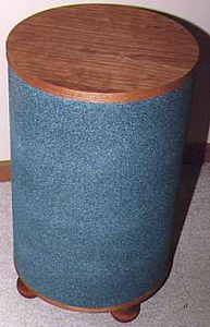
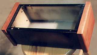
For the
curious, here's what everything looked like at the end.
Design
Goals and Criteria
During part
of 1998, Madisound
sold a driver named the INF-10 at a mere $34 USD. These are
10 inch drivers manufactured by Infinity
Systems. During this time, I became interested in the
construction of cylindrical speaker enclosures. Subwoofers
made from Sonotube, a commercial cardboard tube made
for pouring concrete footings, are fairly popular with the
DIY speaker crowd due to their low cost, simplicity, and high
performance. I decided that the INF-10 driver would be perfect
for a low cost tubular subwoofer.
For more
information on Sonotube subs, check out the Sonotube
FAQ by Gordon McGill.
As with
all my projects, I start with a list of goals which then guides
my design.
- Low
cost. When I started this project, I didn't have a real
need for another subwoofer as I already have a
pair of subs utilizing the NHT 1259. But since my subs
are wired to my main speakers (left/right), I figured this
sub could be connected to the subwoofer output of my Pro-Logic
decoder. Since this was targeted at home theater use and
not for high fidelity, I was willing to sacrifice some quality
for cost.
- Easy
to build. Nothing overly fancy. A tube is about as simple
as it gets, though it turned out to be more difficult to
work with than I had anticipated. This may have been partly
due to the 1/2 inch tube I used instead of the typical 1/4
inch tube. The need to provide an appealing finish also
affected the construction steps, making assembly more difficult.
- Use
existing parts where possible. If you like making stuff,
you know what I mean when I say that I always seem to have
"stuff lying around" waiting to be used. This
goal is also consistent with #1 above.
- Low
end extension to at least 30 Hz. This is, after all,
a subwoofer, so let's make sure it sounds like one.
- Aesthetically
pleasing. Looks count. To me, completing a project means
that it's not only useable, but also presentable. This is
important for SAF :)
- Amplifier
and crossover electronics. Can't forget this. In keeping
with goal #1, the original intent was to use a pair
of National
Semiconductor LM-12 high power op-amps in bridged mode.
I already had a pair... somewhere. All I had to do was build
a multiple-input, variable gain, variable frequency, low-pass
crossover and preamp to drive the LM-12s. This idea was
eventually scrubbed in favor of a Parapix amplifer from
Apex Jr.
The Parapix solution was not only cheaper but required much
less work on my part.
- Downward
firing. A downwards firing subwoofer has some advantages
and disadvantages over a forward firing sub. In this case,
firing down made sense due to the use of the tube. It also
meant not having to worry about grills or prodding fingers
from kids (hopefully). Not all drivers should be used in
a downwards firing position, as this will cause cone sag
over time. How the INF-10 will fare over time, I don't know.
- Decent
SPL capabilities. It needs to have enough output to
enjoy movies.
Technical
Details and Design
Here are
the specs for the INF-10 as published by
Madisound.
I did not measure the actual driver used.
| Impedance |
Fs |
Qts |
Vas |
Xmax |
Efficiency |
Power |
| 8 ohms |
22 hz |
0.34 |
109 liters |
8 mm |
88 dB |
100 W |
The design looks like this :
| Internal Volume |
Port Tuning |
Predicted F3 |
Max SPL @ 30 Hz |
| 2.6 cubic feet |
24 Hz |
26 Hz |
106 dB @ 100 w |
For more
information on the INF-10 driver, see Steve
Houlihan's and Brian
Steele's web sites.
Parts List and Cost
Using the
above guidelines, I assembled parts for the Sonosub from various
sources. Many of the items were things I already had on-hand
(goal #3). Other parts came from the local surplus/recycled
materials dealer.
- 16 inch
(inside diameter) cardboard "storage tube" by
Sonoco, 3 ft long. I found this at a local surplus dealer.
Note that this is not a typical Sonotube. The cardboard
in this tube is 1/2 inch thick, twice the typical 1/4 inch
thick concrete tubes. The thicker wall is nice, but adds
to the weight and is not easy to work with if it's not almost
perfectly round. My tube was almost round. Luckily, the
imperfect parts were at one end, where I was able to simply
shorten the tube by the offending amount. Cost : $2.00
- Funiture
grade plywood in varying sizes averaging 2 ft square. These
also came from the same surplus dealer. Both sides are veneered
with what looks like birch, with an 'A' side and a 'B' side.
Thickness is roughly 3/4 inch though it varied from sample
to sample. Cost : $2.00 per sheet, 2 sheets used.
- Particle
board, 5/8 inch thick. I had remnants of a 2 ft x 4 ft sheet
originally intended for some long-forgotten project. There
was enough for one round endcap. Cost : ?
- Construction
grade plywood, 3/4 inch thick. More remnants. Cost : ?
- 3/8 inch
thick cherry veneered plywood. Yet more remnants. Cost :
?
- Roofing
felt. Leftovers. Cost : ?
- Two 3/8
inch threaded steel rods, 3 ft long; plus washers, lock
washers, and nuts. These came from the local home warehouse.
Cost : $7.00
- An INF-10
driver. Cost : $34, not including s&h.
- A plastic
tube for the vent; 3 inches I.D. by 9 inches long. I was
all set to use a piece of plastic plumbing tube when I realized
I already had just the right size tube. The tube was the
center to a roll of paper from a local paper mill. This
roll happened to be 9 inches wide. Cost : $0.00
- A terminal
cup. I already had one. Cost : ?
- Spray-on
finishes, namely Rustoleum's American Accents Stone Creations
(two cans, $14.00) and Clear Matte spray (one can, $6.00),
plus primer ($3.00). Cost : $23.00
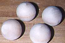
- Ball
feet. A downward firing sub must be elevated. I used four
wooden balls (not entirely round; each had a small flat
part) I already had. I don't know what I originally paid
for them, but I found some at the local crafts store for
about $3.00 each sold as "doll heads". Cost :
$12.00
- Parapix
amplifer, with transformer and wiring connector. At $39.00,
this was a much cheaper and simpler solution than building
my own LM-12 amplifier. The transformer for the LM-12s would
have easily cost $20.00 or more and I would still have a
lot of work to do. With shipping and other charges, the
final cost : $49.00. Note that as of this writing, the Parapix
amplifier is sold out and no longer available from Apex
Jr.
Total cost
is $131.00 of the above itemized goods; darn good for both
a subwoofer and amplifer. Cost could easily have been reduced
further by changing the appearance of the unit - use latex
paint instead of the Stone Creations; use simple wooden blocks
for feet, etc.
Building the Speaker
Below are
the notes I took during construction, plus any tidbits added
via hindsight. The steps are not the most streamlined but
represent the actual steps taken; not the optimal ones. This
gives the feel of what was actually done.
- Note
- in all cutting and milling steps, remember to account
for the "good" side of the stock. Most woodworking
operations have a higher risk of tearing or damaging one
surfaces than the other. Properly orienting the stock can
minimize damage to the important surfaces.
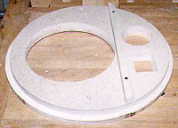
- Make the endcaps.
- Cut
down the tube to the desired length of 24-1/4 inches.
Scribe a line around the tube and cut it with a jigsaw.
Cut from one or both ends of the tube so that any deformation
of the tube (likely near the ends where it's weaker)
is cut off leaving the rounder center portion. Cleaned
up the edge as needed.
- The
tube has an inside diameter of 16 inches. The tube's
wall thickness is 1/2 inch. Each endcap consists of
an inner 16 inch diameter insert and an outer 17 inch
diameter cap.
- Mill
two 16 inch diameter round inserts. I made one from
plywood and one from particle board; it's what I had
on-hand. These must fit snugly inside the tube. Don't
assume the tube is exactly 16 inches in diameter. Make
the inserts to fit, not to what it should be. To determine
the actual inside diameter, I took masking tape, taped
a circle inside the tube until it overlapped itself,
marked the tape where it overlapped, removed it and
measured it with a tape measure. This gave me the exact
circumference. Divide the circumference by pi and get
the diameter.
- In
retrospect, my use of cheap plywood was a bad idea.
While it satisfied my goal of using up stuff I already
had, it lowered the quality of the top endcap. See the
section on results.
-
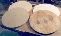 Mill
the two outer round pieces from cabinet grade plywood.
One is the baffle (bottom) the other is the top. I made
them 17 inches in diameter to cover the 1/2 inch thick
tube walls. I should have made them larger so that they
stand a little proud of the walls. This would help hide
any irregularity between the endcaps and the tube wall. Mill
the two outer round pieces from cabinet grade plywood.
One is the baffle (bottom) the other is the top. I made
them 17 inches in diameter to cover the 1/2 inch thick
tube walls. I should have made them larger so that they
stand a little proud of the walls. This would help hide
any irregularity between the endcaps and the tube wall.
- We
now have one small and one large circle for both the
top and bottom. My circle cutting jig uses a 1/4 inch
hole as the center pivot point. This lets me use a 1/4
inch dowel to align each pair of circles at their centers.
-
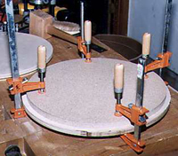 Pick
one of the outer pieces to be the top - probably the
better looking one; put that one aside. Align and two
bottom pieces together to make the baffle. I used regular
yellow wood glue. Clamp and let dry overnight. Pick
one of the outer pieces to be the top - probably the
better looking one; put that one aside. Align and two
bottom pieces together to make the baffle. I used regular
yellow wood glue. Clamp and let dry overnight.
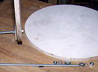
- Complete the top endcap.
- I
used two 3/8 inch diameter metal rods to secure the
two endcaps to the tube and to one-another. Having rods
means that the top and bottom should be aligned relative
to each other. Mark a line on both ends of the tube.
Make sure these marks form a line that is perpendicular
to the top and bottom circular plane.
- Align
the top's inner (smaller) circle with the glued up bottom
assembly and temporarily clamp in place. Drill from
the baffle side (to avoid splitting the good outside
surface) a 3/8 inch hole through all layers. I used
a drill press to get a nice perpendicular hole. Use
a brad point bit to minimize damaging the entry hole.
My holes were 1-1/4 inches from the outer edge of the
baffle. Make sure to place the holes to avoid obstructions
with the driver, port, tube, etc.
- On
the bottom baffle, the rods stick out and that's ok.
On the top, they can't stick out for aesthetic reasons.
The nuts on the top endcap must therefore be hidden
between the top two circles (which is why they've not
been glued together yet).
- Remove
the top's inner (small) circle from the clamps. Now
clamp it to the top's outer (larger) circle and mark
the center of the 3/8 inch holes on the outer circle.
Use another 1/4 inch dowel for alignment.
- It's
probably a good idea to label the 2 rods, especially
if they are not exactly opposite each other on a diameter.
I marked all holes with a "1" and "2".
- Mill
a recess between the two circles that make up the top
endcap. The nuts for the rods will be hidden here. On
the top's inner (smaller) circle, use a 1-1/4 inch diameter
Forstner bit to drill a recess about halfway into the
plywood. This is on the side that will meets the top's
outer circle. The recess must be wide enough to handle
a flat washer.
- On
the top's outer circle, use a 3/4 inch forstner bit
to do the same, using the previously marked center as
a guide. This recess is narrower since it only has to
conceal the 3/8 inch nut, not the washer. The total
depth of both recesses must hold a flat washer, lock
washer and nut.
- Since
the top's smaller circle is now thinner at the hole
due to the recess, I added reinforcement. I glued an
additional layer of plywood to the inside plywood face
and drilled a 3/8 inch hole through it.
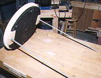
- Cut
down the steel rods to the desired length. I did a dry
fit of everthing to get just the right length. I used
a hacksaw, and filed the rough end smooth for safety.
-
 If cutting the rod leaves that end unusable for threading
a nut and you can't fix it with a grinder, insert a
nut, lock washer and washer from the other end. The
bad end will be the end that's enclosed between the
two top circles and will remain unseen and unused. Thread
the rod from the top, through the top's small circle.
From the other side, add another washer, lock washer,
and nut. Tighten the nuts such that the top nut assembly
fits in the cavity previously drilled.
If cutting the rod leaves that end unusable for threading
a nut and you can't fix it with a grinder, insert a
nut, lock washer and washer from the other end. The
bad end will be the end that's enclosed between the
two top circles and will remain unseen and unused. Thread
the rod from the top, through the top's small circle.
From the other side, add another washer, lock washer,
and nut. Tighten the nuts such that the top nut assembly
fits in the cavity previously drilled.
- With
both rods in place and secured, the top's larger circle
can be aligned with the smaller circle and the recesses
milled into it should cover the protruding 3/8 inch
nuts. If the recesses are too small, take out the drill
and recess deeper, being careful not to cut through
to the other side.
- Align,
glue and clamp the two top pieces together. What I forgot
to do is to fill the void around the nuts assembly with
filler - silicone caulk would have worked. I didn't
realize this until much later and it was too late to
take the assembly apart.
- Drill
3/8 inch hole over the 1/4 inch dowel that's sticking
out of the top piece (outside face). Make 3/8 inch plug
from the appropriate wood using a plug cutter to plug
the hole. This step is purely for looks.
- Add
6 layers of roofing felt on the inside of the top assembly.
These are held by caulk and a few screws. This adds
additional damping on the surface directly opposite
the driver. Total thickness is about 3/8 inch. Why 6
layers you ask ? Because that's what I had on-hand !
-
 What I should have done was to attach bracing to the top
endcap to stiffen it. Then attach the roofing felt to
any remaining flat surfaces. This is probably the single
most important step I omitted during construction.
What I should have done was to attach bracing to the top
endcap to stiffen it. Then attach the roofing felt to
any remaining flat surfaces. This is probably the single
most important step I omitted during construction.
- The
top assembly is now done.
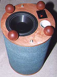
- Complete the bottom endcap (the baffle).
- Now
it's time to work on the bottom endcap, which is also
the baffle. Plan the placement of the driver, port,
terminal cup, bracing and feet onto the baffle.
- Route
a circle into the baffle for the driver's flange. This
is 10-1/8 inch in diameter and 3/16 inch deep. The depth
allows for a gasket to be added.
- Route
the driver opening.This is 9 inch in diameter. For safety,
do this in multiple passes, leaving about 1/4 inch at
the bottom. Remove the remaining 1/4 inch with jigsaw
for safety.
- Mill
3-5/16 inch diameter hole for the plastic port using
a T-shaped circle cutter on a drill press. Like the
driver opening, cut as far down as possible without
going through, remove remainder with jigsaw.
-
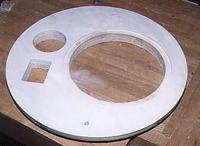 Cut a 2-7/8 x 2-1/8 inch opening for a rectangular terminal
cup. Do this with a jigsaw.
Cut a 2-7/8 x 2-1/8 inch opening for a rectangular terminal
cup. Do this with a jigsaw.
-
 Glue and screw a hardwood bar on the inside of the baffle.
This bracing helps stiffen the baffle, compensating
for the loss of so much material that's been removed.
Depending on the layout of holes on the baffle, there
may not be room for any bracing, or multiple braces
may have to be used. The particle board I used was pretty
good material. Void-free plywood would have been structurally
stronger.
Glue and screw a hardwood bar on the inside of the baffle.
This bracing helps stiffen the baffle, compensating
for the loss of so much material that's been removed.
Depending on the layout of holes on the baffle, there
may not be room for any bracing, or multiple braces
may have to be used. The particle board I used was pretty
good material. Void-free plywood would have been structurally
stronger.
- Add
alignment marks to both the top and bottom endcap assemblies.
These will be used to align top and bottom with the
mark on the tube.
- Work on the cardboard tube.
- The
cardboard tube's outer skin is a spiral layer of thick
paper/cardboard. Each winding of the spiral overlaps
the previous one by a little bit. To make the tube completely
smooth, these overlapping regions must be made flush
with the rest of the tube. Shave (with a block plane)
the overlapping regions of the cardboard tube. Sand
as needed.
- Use
vinyl spackle to patch up all rough areas and other
dinks, scratches, etc. (this was after all a surplus
tube). Sand the result to 220 grit sandpaper.
-
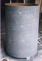 Prime the exterior tube surface with a spray primer.
-
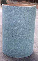 Spray the exterior with 2 cans of Rustoleum's Stone Creations
(greenish tint). Seal with one can of Rustoleum American
Accent matte finish clearcoat.
Spray the exterior with 2 cans of Rustoleum's Stone Creations
(greenish tint). Seal with one can of Rustoleum American
Accent matte finish clearcoat.
- At this
point, I evaluated the appearance of the endcaps. The top
was furniture grade plywood, but I wanted a cherry look
to better contrast with the granite green finish of the
tube. The veneer was birch, and when I applied a cherry
stain, it looked horrible. So I decided to add another layer
of cherry veneer plywood I already had.
- Glue
3/8 inch thick cherry veneered plywood to the top endcap.
Use a router with a pattern following bit to cut the
plywood flush with the existing endcap.
- For
the exposed edges, apply cherry edge banding to both
endcaps. This is an iron-on strip of real wood veneer
with pre-applied, heat activated glue.
- Applied
Watco Danish oil to cherry surfaces. Topcoat with a
thin layer of wax.
- Final assembly.
- Glue
the plastic port tube to the bottom endcap/baffle using
RooClear plastic glue.
- Attach
two wires from the inside of the terminal cup. Solder
connectors to the driver ends of the wires to allow
easy connect/disconnect to/from the driver.
- Mount
the rectangular terminal cup to bottom endcap/baffle
with four screws. Use a small amount of rope caulk to
give it a good seat in the hole.
- Connect
the endcaps to the tube. On the first pass, I used rope
caulk to seal the endcap/tube interface. Later I glued
the tube to the endcaps making it effectively impossible
to disassemble the unit without destroying something.
Add a flat washer, lock washer and tighten the nuts
on the rods.
- Feet
-
 To raise the unit off the ground (after all, this is a
downward firing sub) I made feet out of 4 hardwood balls.
These have a flat part and are sold as doll heads in
craft stores (they may also be sold for other purposes).
The ones I used are 3 inches in diameter.
To raise the unit off the ground (after all, this is a
downward firing sub) I made feet out of 4 hardwood balls.
These have a flat part and are sold as doll heads in
craft stores (they may also be sold for other purposes).
The ones I used are 3 inches in diameter.
- To
mount the flat part of the ball to the baffle, I made
a drilling jig. I drilled a 3/8 inch diameter hole through
a block of scrap wood to make the jig. The purpose of
the jig is to guide a drill bit perpendicularly into
the ball.
- Locate
the center of each ball's flat area. Position the hole
of the jig over the center of each foot and using the
jig as a drilling guide, drill a 3/8 inch diameter hole
about 1-1/2 inch deep hole into each ball.
-
 Cut four lengths of 3/8 inch threaded rod from stock left-over
from the main conneting rods. These should be long enough
to go from the balls, through the baffle, and stick
out the other side with clearance for a flat washer,
lock washer and nut assembly.
Cut four lengths of 3/8 inch threaded rod from stock left-over
from the main conneting rods. These should be long enough
to go from the balls, through the baffle, and stick
out the other side with clearance for a flat washer,
lock washer and nut assembly.
- Epoxy
a piece of 3/8 inch threaded rod into each ball.
- To
locate the four feet accurately on the baffle, I made
another jig. This was 2 pieces of wood, half-lapped
onto one-another at right angle (makes a large '+' sign).
I marked off the radius from the center of the jig and
moved the jig about the baffle until all four sides
were equi-distant from the center based on the markings.
- Drill
3/8 inch diameter holes through the baffle for the feet
- Mount
and secure the feet with a flat washer, lock washer
and nut on the inside of the tube. Reach in through
the driver opening to do this.
- Lastly.
- Vaccum
out the interior in case there's debris still hiding
in there.
- Mount
driver to the baffle. The supplied gasket is pretty
useless so use rope caulk. Connect the wiring, then
screw the driver down.
- Retraced steps.
- As
noted in the results section below, there was
excessive vibration on the tube and top endcap. I decided
to take the tube assembly apart and try and damp out
the vibration without having to rebuild the endcaps.
I added a layer of 6 lb carpet padding to the inside
surface of the tube. This was glued in place.
- The
tube was then glued to the endcaps with Liquid Nails
construction adhesive.
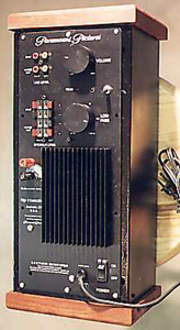
Building the Amplifier
There wasn't
much to do on the Parapix amplifier. The modules arrived almost
ready to use. Here's what I did :
- Modifications
to the amplifier.
- The
best place to obtain infomation on the Parapix amp is
on the Apex
Jr. web page.
- I
used a 48 VCT 3 Amp transformer, which mounted directly
to the component side of the Parapix faceplate on two
of the existing mouting holes.
- For
the power wiring harness, I connected five of the six
wires (two for the primary, three for the seconday of
the transformer). I decided not to wire pin 1.
- The
amp jumper is set to bridge mode.
- Since
the amp is external to the subwoofer, I needed two connectors
for the amp's output. I mounted a pair of 5-way binding
posts from Radio
Shack to the faceplate where the Paramount logo
sits. I spaced them 3/4 inch apart for use with standard
dual plugs.
- Next
to the Peak LED (between the two knobs), I drilled
a 1/4 inch hole and mounted a plastic T1-3/4 LED retainer
to hold the Power LED.
-
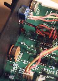 Next to the LEDs, I mounted a SPDT switch. Three wires from
the switch were connected to a pair of headers salvaged
from the original metal housing (see below). These headers
go to the three pins of the boost circuitry. This allows
the user to enable or disable the boost rather than
hiding this feature on the amplifier PCB. Make sure
to mount the boost switch to make sense - up for boost
on, down for boost off.
Next to the LEDs, I mounted a SPDT switch. Three wires from
the switch were connected to a pair of headers salvaged
from the original metal housing (see below). These headers
go to the three pins of the boost circuitry. This allows
the user to enable or disable the boost rather than
hiding this feature on the amplifier PCB. Make sure
to mount the boost switch to make sense - up for boost
on, down for boost off.
- Housing for the amplifier.
-
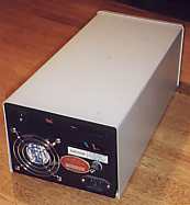 The metal casing is from an old Exabyte 8 mm tape drive
whose mechanisms have long ago seen the local land fill.
The only parts I kept were the 3 sided metal casing
and some wiring (see above).
The metal casing is from an old Exabyte 8 mm tape drive
whose mechanisms have long ago seen the local land fill.
The only parts I kept were the 3 sided metal casing
and some wiring (see above).
- For
the two ends, I milled endcaps much like the subwoofer
(of course !). Each endcap has a solid cherry outer
piece and a smaller particle board inner piece. The
inner piece is screwed to the outer cap and also to
the metal casing.
- The
amplifier module is mouted to the inner particle board
pieces with screws.
-
 Black spray paint and a clearcoat was applied to the metal
casing to match the black Parapix faceplate. The cherry
endcaps received a coating of Danish oil and wax; same
as the subwoofer.
Black spray paint and a clearcoat was applied to the metal
casing to match the black Parapix faceplate. The cherry
endcaps received a coating of Danish oil and wax; same
as the subwoofer.
Results
To test
the subwoofer, I used the line level output of my PC sound
card (Turtle Beach Malibu)
to drive a Rotel amplifier. Later I repeated this test with
the Parapix amp. This particular sound card has decent low
end extension (see test results at the PC
AV Tech web site) so I wasn't worried that it would limit
the low end test signal.
When I cranked
the volume up, I noticed that the tube wall and top endcap
vibrated. This should not happen with a tubular enclosure.
Adding mass to the top decreased the vibration; sitting on
it removed all of it. I concluded that I did not do an adequate
job of strengthening the top endcap - there was no bracing,
the inner circle was low grade plywood, and as mentioned previously,
I had neglected to fill the void where the nuts are hidden.
I tried
to do what I could short of ripping things apart. I glued
the tube to the endcaps, and added carpet padding to the tube
walls. This seemed to help a wee bit, but the walls still
vibrated. The real solution was to rebuild the endcap. Since
I didn't have the time to do this, I decided to place the
subwoofer into service and worry about it some other time
- hey, this is DIY, which means things are never really done
!
No measurements
were ever made. Instead I simply listened, looked,and felt
the results. It was pretty obvious that the frequency response
cutoff was in the mid to upper 20's as predicted. As for SPL,
it can definitely crank but it didn't take much to reach the
driver's excursion limit. Nonetheless, the SPL at that point
is more than enough for HT use in a "typical" room.
|
|
29-September-2000
Note: The
contents in these pages are provided without any guarantee,
written or implied. Readers are free to use them at their
own risk, for personal use only. No commercial use is allowed
without prior written consent from the author.
|
|
 |